Mocking is an essential part of unit testing, and the Mockito library makes it easy to write clean and intuitive unit tests for your Java code.
Get started with mocking and improve your application tests using our Mockito guide:
Handling concurrency in an application can be a tricky process with many potential pitfalls. A solid grasp of the fundamentals will go a long way to help minimize these issues.
Get started with understanding multi-threaded applications with our Java Concurrency guide:
Spring 5 added support for reactive programming with the Spring WebFlux module, which has been improved upon ever since. Get started with the Reactor project basics and reactive programming in Spring Boot:
Since its introduction in Java 8, the Stream API has become a staple of Java development. The basic operations like iterating, filtering, mapping sequences of elements are deceptively simple to use.
But these can also be overused and fall into some common pitfalls.
To get a better understanding on how Streams work and how to combine them with other language features, check out our guide to Java Streams:
Explore Spring Boot 3 and Spring 6 in-depth through building a full REST API with the framework:
Yes, Spring Security can be complex, from the more advanced functionality within the Core to the deep OAuth support in the framework.
I built the security material as two full courses - Core and OAuth, to get practical with these more complex scenarios. We explore when and how to use each feature and code through it on the backing project.
You can explore the course here:
All Access is finally out, with all of my Spring courses. Learn JUnit is out as well, and Learn Maven is coming fast. And, of course, quite a bit more affordable. Finally.
>> GET THE COURSE
Spring Data JPA is a great way to handle the complexity of JPA with the powerful simplicity of Spring Boot.
Get started with Spring Data JPA through the guided reference course:
Refactor Java code safely — and automatically — with OpenRewrite.
Refactoring big codebases by hand is slow, risky, and easy to put off. That’s where OpenRewrite comes in. The open-source framework for large-scale, automated code transformations helps teams modernize safely and consistently.
Each month, the creators and maintainers of OpenRewrite at Moderne run live, hands-on training sessions — one for newcomers and one for experienced users. You’ll see how recipes work, how to apply them across projects, and how to modernize code with confidence.
Join the next session, bring your questions, and learn how to automate the kind of work that usually eats your sprint time.
1. Overview
While design tools and development aren’t always compatible, being able to programmatically generate schematic images and diagrams can be invaluable.
In this tutorial, we’ll explore a few approaches for generating UML diagrams from Java code. First, we’ll start with static analysis tools that scan source or bytecode to produce class and dependency diagrams automatically. Then, we’ll look at tools and frameworks that help us expose architectural boundaries in one way or another. Finally, we’ll explore an agent-based approach that uses an LLM to turn a code diff into a diagram and a human-readable summary.
To facilitate and expand the overall understanding, we’ll use these various approaches to generate different types of diagrams for a demo application. It’s built with a vertical slice architecture, modeling a domain that simulates a blogging platform like Baeldung itself.
2. Why UML Diagrams
Pull requests have been getting larger. AI-assisted coding tools make it easy to touch a dozen classes across several packages in a single commit. New interfaces extracted, dependencies rewired, responsibilities moved between layers — all generated in minutes rather than hours.
As a result, code review is increasingly becoming the bottleneck. Mainly, that’s because reviewers are expected to reconstruct the shape of a change from the diff alone. However, a diff that’s readable line by line doesn’t necessarily make the change easy to understand. Scrolling through additions and deletions gives little sense of which classes now depend on which. Also, components can often quietly cross a boundary they shouldn’t.
This is exactly the kind of problem diagrams are designed to solve. A good diagram can provide the reviewer with a structural summary before they read a single line of the methods section. It shows which components were added, which relationships changed, and where the blast radius of the change actually is. Generating that diagram from the before-and-after state of a change — or straight from the diff — turns a wall of text into something you can take in at a glance.
3. Static Code Analysis
The most deterministic way to get a diagram is to generate it directly from the code — no manual modeling, no LLM in the loop, just a tool that walks the class files or source tree and emits a diagram description. These tools work by parsing imports, package structure, and class relationships, then rendering the result as PlantUML or Mermaid.
IntelliJ IDEA ships with built-in diagram support that can visualize a package, a module, or the classes touched by a selected diff.
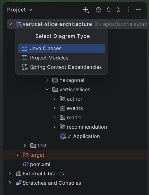
Let’s see the steps to generate a Java class diagram directly from a classic IDE:
- Right-click the root directory of the project, or a Java package
- Select Diagrams > Show Diagrams
- Select Java Classes as the type of diagram we want to generate
This is all done in a single subwindow:
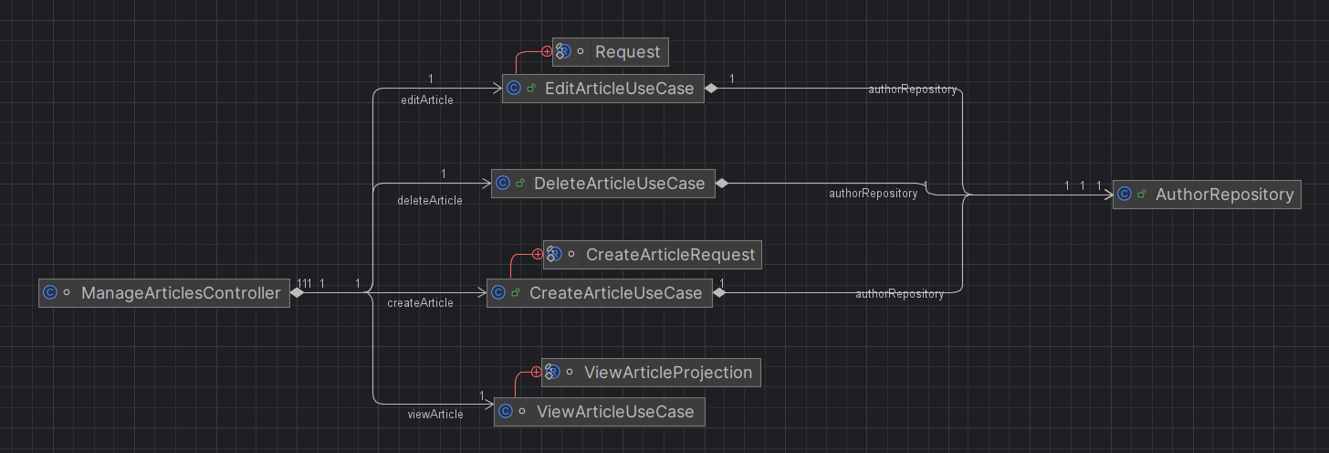
IntelliJ should now render the class diagram in a separate tab. The diagram is interactive rather than exported by default, but it can be saved as a .png, .svg, or .puml file via the toolbar’s export button:
Alternatively, we can use an IDE plugin such as PlantUML Parser, which lets us right-click any Java file or directory, select PlantUML Parser, and generate a .puml file directly:
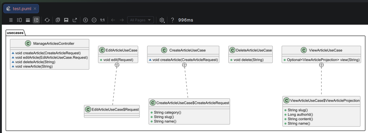
Needless to say, there are plenty of other options too. Teams still relying on Eclipse have their own options too, with older plugins like AmaterasUML solving the same problem within that IDE.
Outside the IDE, Java2PlantUML takes a similar approach from the command line, scanning compiled bytecode or source and producing a .puml file, which makes it a good fit for CI pipelines.
4. Framework-Level Architecture Sources
Static analysis tools have no notion of intent — they see classes and packages, not architectural boundaries. Some frameworks, however, already know exactly where those boundaries are, because we declared them explicitly.
Rather than reverse-engineering structure from bytecode, we can treat these framework-level declarations as ground truth for diagrams. Some of these frameworks go a step further too, letting us highlight and even enforce those boundaries as part of the build itself.
Spring Modulith is a good example of this. Specifically, Spring Modulith lets us organize a Spring Boot application into explicit modules, one per top-level package, and verifies at build time that modules only interact through their public API:
class ModularityTests {

    ApplicationModules modules = ApplicationModules.of(Application.class);

    @Test
    void verifiesModularStructure() {
        modules.verify();
    }

    @Test
    void createModuleDocumentation() {
        new Documenter(modules).writeDocumentation();
    }
}
As we can see, apart from just verifying the structure of modules, we can also generate documentation directly from it. Running createModuleDocumentation(), produces a set of PlantUML diagrams in target/spring-modulith-docs:
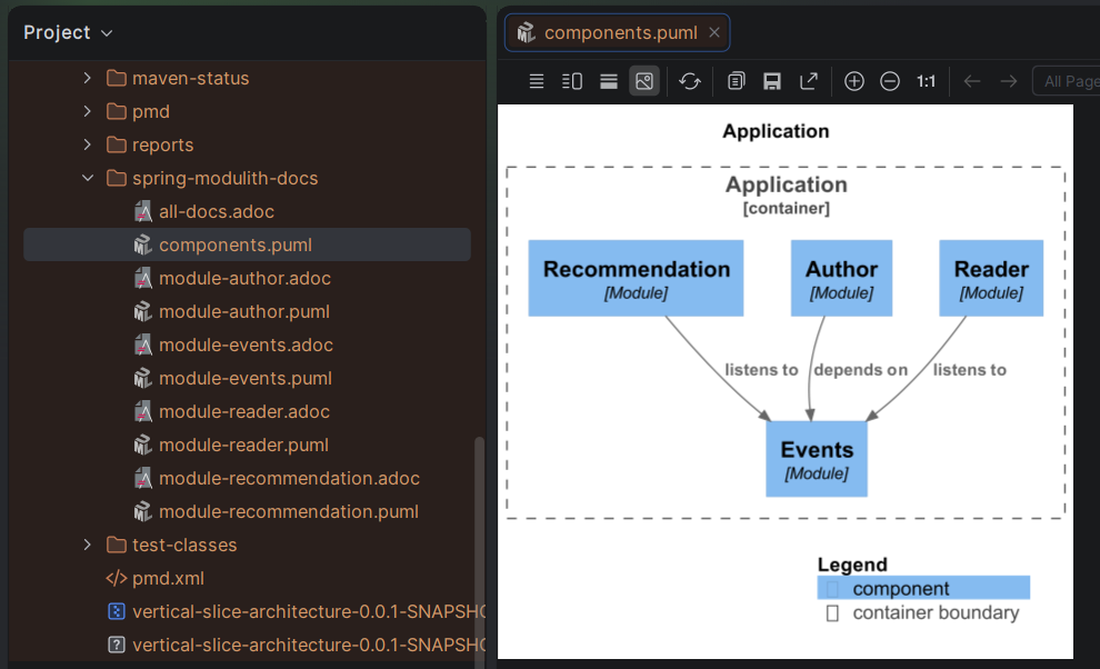
Other frameworks such as Spring Cloud Stream enable us to declaratively define the flow of data through the application in a single, centralized configuration file. Since these bindings live in one place rather than scattered across annotations, we can easily read that file and generate a sequence or flow diagram in Mermaid or PlantUML to show how data moves between services.
While these frameworks help us document what’s happening inside a single service, they don’t tell us much about how that service talks to the outside world — that’s where contracts come in. Scanning contract files can be a good way to understand how different services connect. This includes OpenAPI and AsyncAPI docs, or Spring Cloud Contract and Pact contracts, if we implement contract testing.
5. Agent-in-the-Loop Generation
Static analysis and framework-level sources both have limitations. In essence, they can only describe structure that already exists in a machine-readable form. Neither can tell us why a change was made, or summarize it in plain language for the reviewer.
This is where an LLM-based agent fits in. Rather than parsing code deterministically, we can trigger a lightweight agent like Claude Haiku. It reads a diff directly and produces both a diagram and a short, human-readable summary of what changed. There are two natural places to wire this in.
The first is as a step in a CI pipeline, e.g., a GitHub Actions or GitLab CI job that runs on every pull request, diffs against the target branch, and posts the generated diagram and summary as a PR comment:
- name: Generate PR diagram and summary
  run: |
    git diff origin/main...HEAD > diff.patch
    claude -p "Given this diff, generate a Mermaid diagram of the
    affected components and a 2-3 sentence summary of the change." \
    diff.patch > pr-summary.md
On the other hand, we can also use a pre-commit hook that uses a local AI harness like Claude Code or the Copilot CLI, so the documentation is generated and committed alongside the change itself.
Let’s see a simplified version of such a hook, which we can save as .githooks/pre-commit:
#!/bin/bash
DOCS_FILE="docs/$(git branch --show-current | tr '/' '-').md"
DIFF=$(git diff --cached | head -c 4000)
[ -z "$DIFF" ] && exit 0

PROMPT="Generate a brief Markdown doc for this commit: a Summary,
Modified Components list, and a Mermaid Component Diagram.
Changes:
${DIFF}"

claude --model claude-haiku-4-5-20251001 -p "$PROMPT" --output-format text > "$DOCS_FILE" \
  && git add "$DOCS_FILE"
On every commit that touches the project, the hook performs several actions:
- diffs the staged changes
- asks Claude Haiku for a short summary and a Mermaid component diagram
- stages the resulting Markdown file alongside the commit
Let’s commit a few local changes to the codebase and see the pre-commit hook in action:
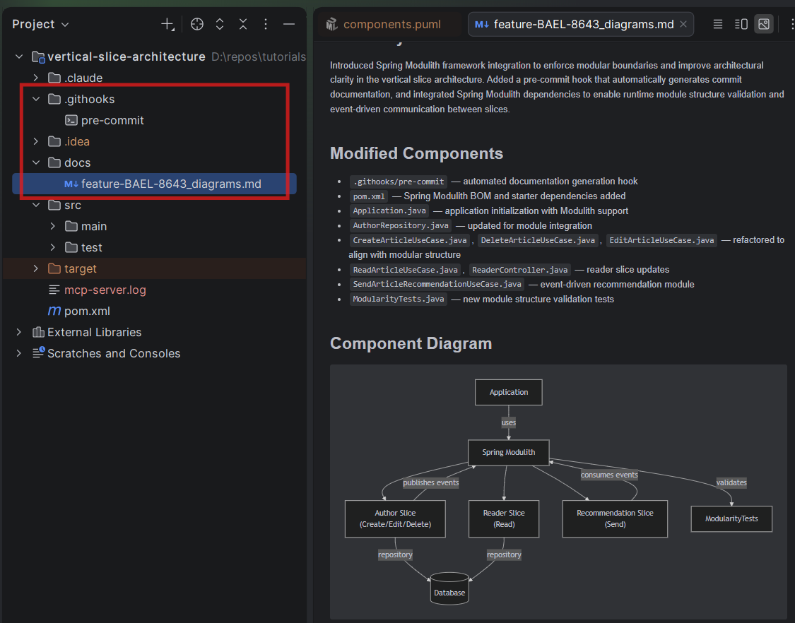
As expected, the model summarizes the changes and generates a simple diagram of the key components affected by the recent commit, making the reviewer’s job easier.
6. Conclusion
In this article, we explored a few ways to generate diagrams from Java code to make code review easier as diffs grow larger and harder to reason about from raw code alone. Initially, we started with static code analysis, using tools like the built-in IntelliJ diagram support, the PlantUML Parser plugin, and Java2 PlantUML to generate diagrams directly from source or bytecode.
After that, we looked at framework-level architecture sources, where tools like Spring Modulith and Spring Cloud Stream let us treat already-declared boundaries and data flows as ground truth for diagrams. Then, we also discussed how contracts like OpenAPI, AsyncAPI, or Pact can document the interactions between services.
Finally, we explored an agent-in-the-loop approach, triggering a lightweight AI agent from a CI pipeline or a pre-commit hook to turn a diff into a diagram and a human-readable summary.