Learn through the super-clean Baeldung Pro experience:
>> Membership and Baeldung Pro.
No ads, dark-mode and 6 months free of IntelliJ Idea Ultimate to start with.
Last updated: March 26, 2025

Learn through the super-clean Baeldung Pro experience:
>> Membership and Baeldung Pro.
No ads, dark-mode and 6 months free of IntelliJ Idea Ultimate to start with.
In this tutorial, we’ll discuss the sub-layers of the Data Link Layer (DLL) of the OSI model.
In order to enable the design of flexible, robust, and interoperable networks, the Open System Interconnection (OSI) model was established. The OSI model consists of seven separate but related layers. The second of these layers is the Data Link layer (DLL), located between the physical layer (first layer) and the network layer (third layer).
The Internet consists of many hosts and connected devices known as the nodes and networks known as the links. The DLL creates and delivers frames from one node to another along a link.
The main functions of the DLL are:
The DLL is divided into two sub-layers to organize its operations and the services provided:
First, let us understand the types of links that operate in the DLL, as discussed in the following section.
There are two categories of links in the DLL:
The DL uses only a part of the link capacity from one point to another. So, it is a point-to-point link. On the other hand, the BL uses all the capacity of a link shared among several users.
The LLC sub-layer deals with issues common to the DL and BL, while the MAC sub-layer deals only with challenges specific to the BL.
Let’s see how a typical DLL Sub-Layer block diagram looks like:
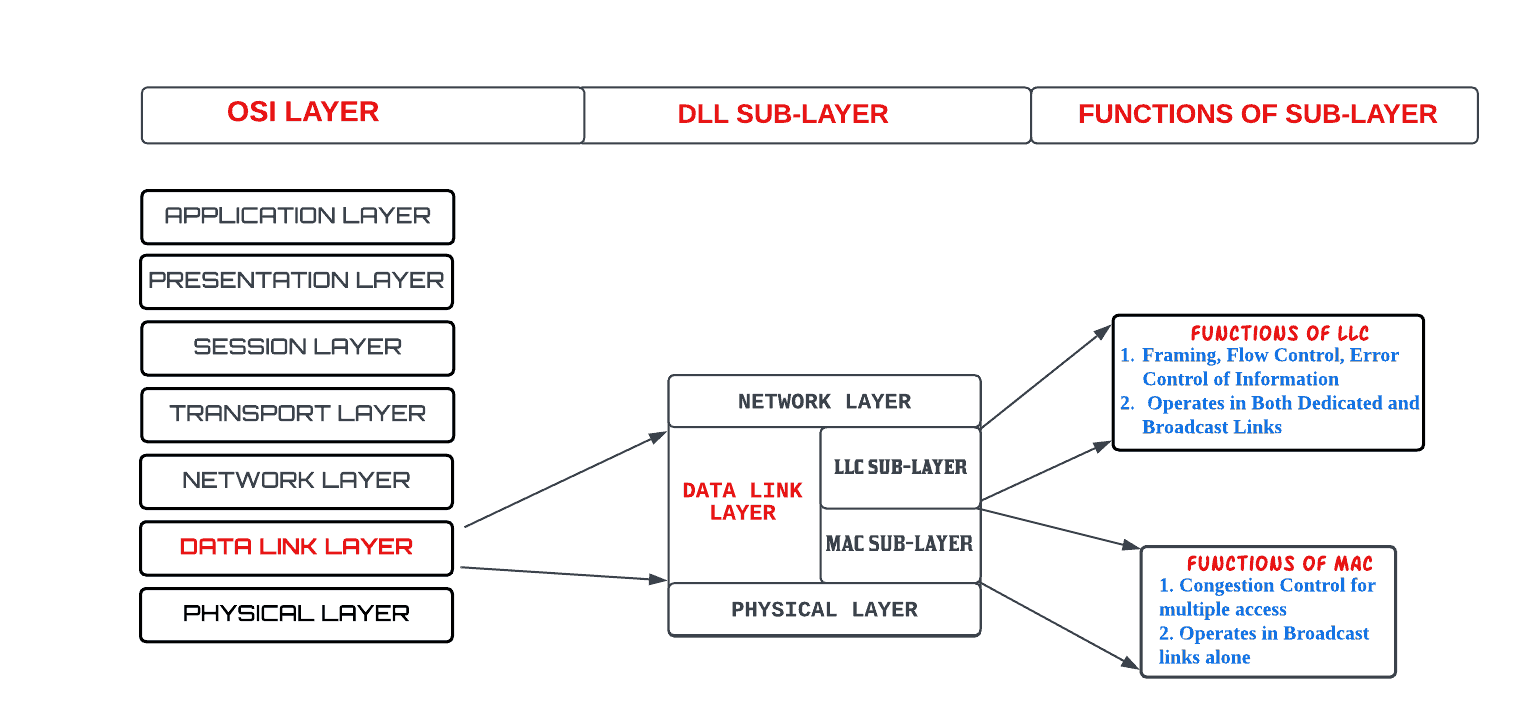
The Logical Link Control (LLC) sub-layer is the upper sub-layer of the DLL. The LLC deals with procedures for communication between two adjacent nodes, whether a DL or BL.
The LLC executes three main functions: Framing, Flow Control, and Error Control. We discuss them in subsections next.
Also known as packetization, the purpose of framing a message is to separate such message from one source to a destination by adding a Sender Address (SA) and a Destination Address (DA). The DA defines where the packet will go; the SA helps the recipient acknowledge receiving the frame.
A message frame is divided into sub-frame for easy flow and error control. The sizes of the sub-frames could be fixed-sized or variable-sized.
In fixed-size sub-frames, there is no need to create a boundary of the two frames; Variable-size sub-frames use a delimiter (flag) to define the boundary of two frames.
Variable-size framing uses two categories of protocols:
In byte-oriented protocol, the data section of a frame is a sequence of bytes. To avoid the flag being part of the information being sent, a byte-stuffing strategy, which is a process of adding one extra byte whenever there is a flag or escape character in the text being sent, is used.
In bit-oriented protocol, the data section of a frame is a sequence of bits. A bit-stuffing strategy is used to prevent the pattern of the flag from looking like part of the message. Bit-stuffing is the process of adding one extra 0 whenever five consecutive 1s follow a 0 in the data so that the receiver does not mistake the pattern 0111110 for a flag.
At the DLL, Flow Control means creating a balance between the frames sent by a node and the frames that can be handled by the next node. One of the used methods for flow control is the use of buffers, one at the sending DLL and the other at the receiving DLL. A Buffer is a set of memory locations that can hold packets at the sender and receiver.
Error control is implemented at the DLL to prevent the receiving node from delivering corrupted packets to its Network layer. Error control implementation at the DLL is simple using two methods: Corrupted frames are silently discarded; uncorrupted frames are accepted with or without sending acknowledgments to the sender.
In both methods, a Cyclic Redundancy Check (CRC) is added to the frame header by the sender and checked by the receiver.
A protocol is a set of specific rules that terminals at each end of a link are required to follow when converting a received or sent message into a serial bit stream.
In the LLC sub-layer of the DLL, all protocols used could either be connectionless or connection-oriented.
In a connectionless protocol, frames are sent from one node to the next without any relationship between the frames; each frame is independent.
In a connection-oriented protocol, a logical connection will first be established between the two nodes before sending the data frames. After all related frames are transmitted, the logical connection is terminated.
There are two primary types of LLC sub-layer protocols:
PAR protocol usually waits for an acknowledgment reply, and the sender retransmits the frame if there is no reply before the reply timer expires.
The ARQ protocol, in turn, is divided into two protocols:
There are both flow and error controls, but communication is a frame at a time in the stop-and-wait protocol.
The pipeline protocol, however, is divided further into two:
In the go-back-n protocol, the receiver must receive the frames in sequential order, while frames may not be received in sequential order in the selective retransmission protocol.
The major function of the MAC sub-layer is congestion control. When nodes are connected and use a common link, this is known as a Broadcast Link (BL). There is a need for Multiple-Access (MA) protocols to coordinate access to this link. The MAC sub-layer handles this coordination.
The MAC layer receives framed data from the LLC layer and reframes the data, adding a source and destination physical address or MAC address to the frame for transmission.
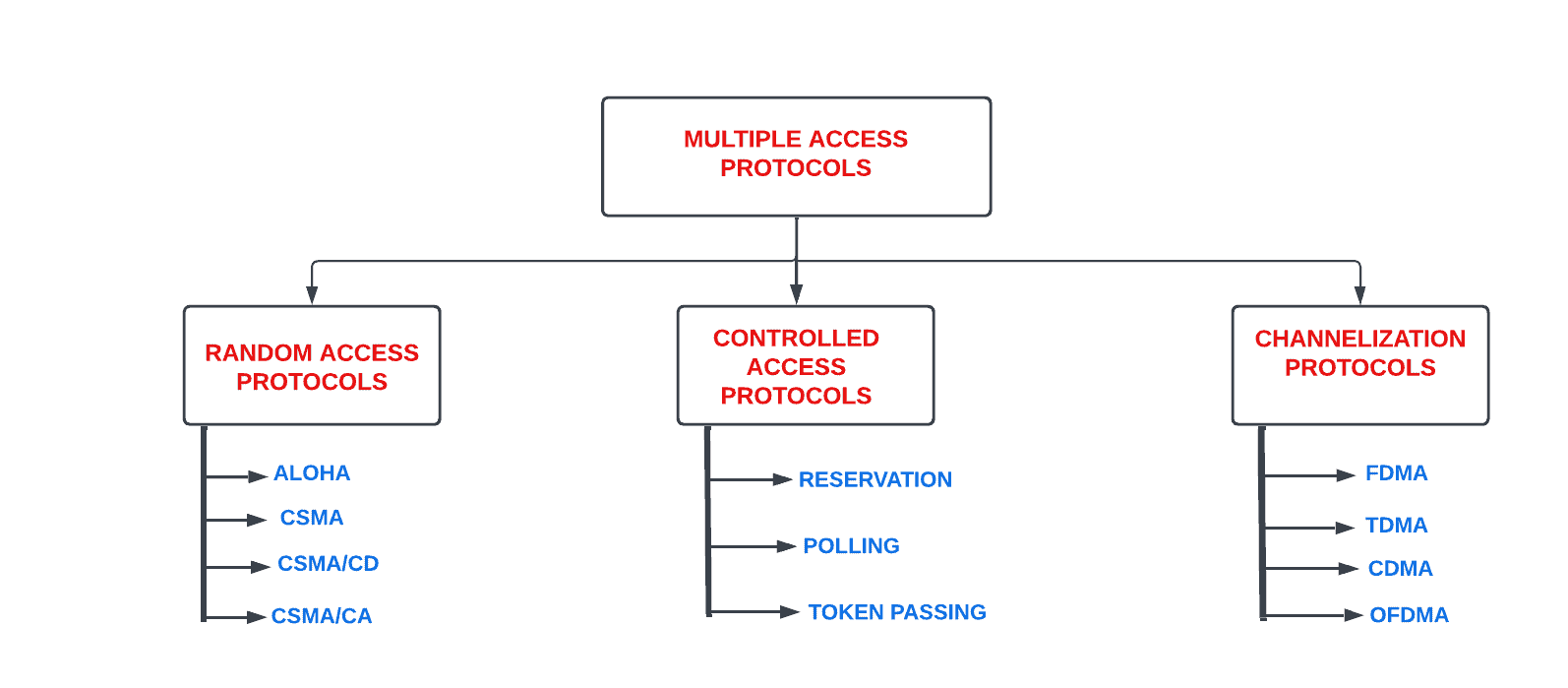
Many protocols belonging to the MAC sub-layer have been devised to handle access to a shared link. These protocols are broadly divided into three groups:
The figure next shows the complete taxonomy of the MAC sub-layer protocols:
The following subsections discuss each group briefly.
In the RAPs, also known as the contention protocols, no node is superior to another node, and none is assigned control over the other. Four methods of protocols are used to implement the RAPs:
The earliest of the RAPs is the ALOHA which uses a simple procedure known as Multiple Access (MA).
To minimize the chance of collision while using the ALOHA, the Carrier Sense Multiple Access (CSMA) was invented. CSMA forces the node to sense the medium before transmitting.
The CSMA method later evolved into two parallel methods: Carrier Sense Multiple Access with Collision Detection (CSMA/CD), which tells the node what to do when a collision is detected, and Carrier Sense Multiple Access with Collision Avoidance (CSMA/CA), which tries to avoid the collision.
In CAPs, the nodes consult one another to find which station node has the right to send. A node cannot send unless it has been authorized by other nodes.
There are three popular CAPs methods:
In the reservation access method, a node needs to make a reservation before sending data. So, time is divided into intervals. In each interval, a reservation frame precedes the data frames sent.
The Polling access method works with topologies in which one device is designated as a primary node and the other devices are secondary nodes. All data exchanges must be made through the primary device even when the ultimate destination is a secondary device. The primary device controls the link; the secondary devices follow its instructions. It is up to the primary device to determine which device is allowed to use the channel at a given time. The primary device is therefore always the initiator of a session.
In the token-passing access method, the nodes in a network are organized in a logical ring. Each station has a predecessor and a successor. A special packet called a token circulates through the ring. The token dictates the right to access the channel from one node to the other.
CPs are multiple-access methods in which the available bandwidth of a link is shared in time, frequency, or through code between different nodes. There are four popular CPs:
In FDMA, the available bandwidth is divided into frequency bands. Each node is allocated a band to send data. It means that each band is reserved for a specific node, belonging to this node all the time.
In TDMA, the nodes share the bandwidth of the channel in time. Each node is allocated a time slot during which it can send data.
In CDMA, the nodes use different codes to achieve multiple access. It is based on coding theory and uses sequences of numbers called chips.
OFDMA combines FDMA and TDMA. So, the resources are partitioned in the time-frequency space. It allows for the accommodation of more users in the shared link than using only FDMA or TDMA.
In this tutorial, we discussed the sub-layers of the Data Link layer (DLL) of the OSI Model. The protocols that make each sub-layer functionally operational were also investigated.