

Learn through the super-clean Baeldung Pro experience:
>> Membership and Baeldung Pro.
No ads, dark-mode and 6 months free of IntelliJ Idea Ultimate to start with.
Learn through the super-clean Baeldung Pro experience:
>> Membership and Baeldung Pro.
No ads, dark-mode and 6 months free of IntelliJ Idea Ultimate to start with.
The OSI model stands for Open Systems Interconnection model and is a standardized framework that describes a networking system’s communication functions. It consists of 7 layers, and each layer has specific functionality to perform.
In this tutorial, we’ll discuss the OSI model and its layers in detail. We’ll present the description and functionality of each layer.
In the early days of networking systems, the networking devices were limited to communicate to the devices manufactured by the same vendors. For example, a networking device manufactured by a company X could only communicate with other devices manufactured by the same company, not with any other companies’ devices.
To ensure that the networking devices manufactured nationally and internationally can communicate with each other, the devices should be developed through a standard procedure. To bring standardization in the computing and communication system, the International Organization for Standardization (ISO) published the OSI model in 1984.
The OSI model consists of 7 layers: Application Layer, Presentation Layer, Session Layer, Transport Layer, Network Layer, Datalink Layer, Physical Layer. Each of these layers has a different role to play, and they work collaboratively to transmit the data from one networking device to another.
Let’s see how the OSI model:
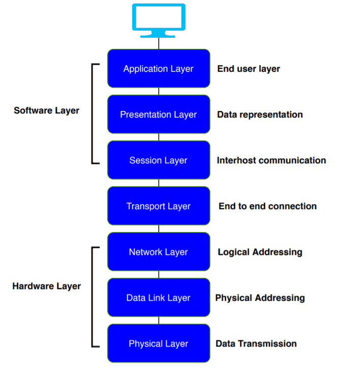
Now, we’ll discuss the primary function of each of the layer:
The lowest layer in the OSI model, the physical layer, is responsible for the transmission and reception of raw data between the network devices and the transmission medium. It stores the information or data in the form of bits and transit bits from one node to another:
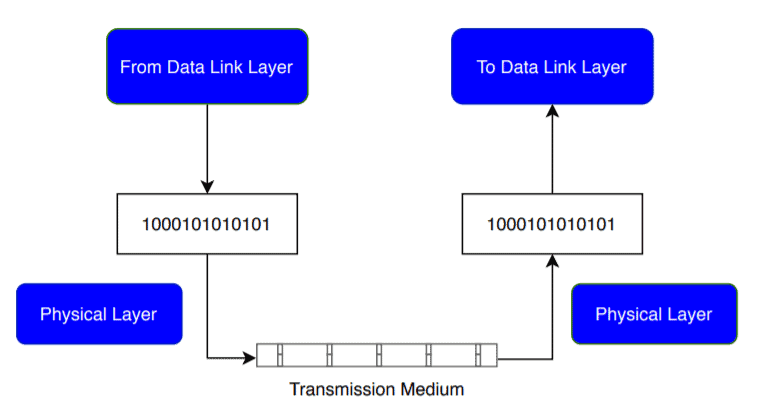
The physical layer plays a vital role in controlling the transmission rate. Whenever some device sends data to the physical layer, it receives the data, converts the data to bits, and sends the data link layer. While transferring the bits, it defines the number of bits transmitted per second.
It facilitates the synchronization at the bit level by setting a clock that controls both the receivers and senders.
It defines the transmission mode in which the data flows between two networking devices.
The physical layer also defines the physical topology. A physical topology is an actual layout of the computer cables and other network devices.
The network protocols which are used in the physical layer are RS-232, UTP cables, DSL.
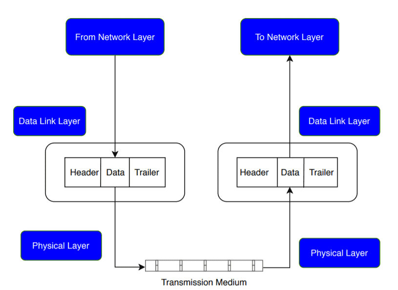
The data link layer is responsible for the data transfer between two directly connected nodes. When the physical layer receives data, it converts it to bits and sends it to the data link layer. The data link layer ensures the data or packet received from the physical layer is error-free and then transfers the data from one node to another. It sends the packet to another node using its MAC address.
The data link layer is further divided into two sub-layers: Logical Link Control (LLC) and Media Access Control (MAC). The LLC layer is responsible for checking the errors in the received packet, and it synchronizes the frames. The MAC layer controls the access of networking devices to the transmission medium. It also gives permission to transfer the data from one node to another.
As soon as the raw data from the physical layer reaches the data link layer, it converts the raw data into packets, called frames. With a frame, it also adds a header and trailer. A header and trailer include information for hardware destination and source address. In this way, it also helps the packet to reach the destination:
The primary responsibility of the data link layer is to control the flow of the data. Suppose some data is transferred from one high processing server to another low processing server. The data link layer makes sure the data rate matches between two servers and no data get corrupted.
The data link layer is also responsible for error control and access control.
The most popular computer networking technology used in the data link layer is Ethernet.
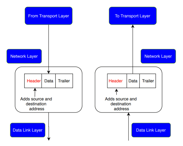
The network layer transmits data from one transmitting station to another. It also helps select the shortest path from one host to another to deliver the data at the best possible time. This process is called routing. It also puts the IP addresses of the sender and receiver into the header.
The network layer provides a logical connection between different network devices. It also plays an important role in addressing. When the incoming data arrives at the network layer, it adds the destination and source address with the header:
The network layers use various protocols like IPv4/IPv6, ARP, ICMP to carry out its functionalities.
The transport layer works between the network layer and the application layer. It ensures the end-to-end and complete transfer of the data. It also provides acknowledgment to the sender node when the data transmission is complete. If there is an error occurred during transmission, the transport layer re-transmit the data.
The transport layer receives the packets from the network layer and divides the packets into smaller packets, known as segments. This process is called segmentation. It also controls the flow and error of the data and helps data to reach the receiver end successfully:
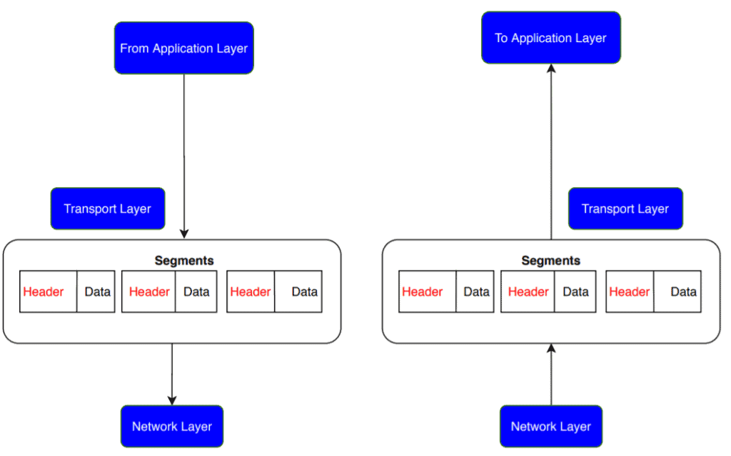
At the receiver’s end, the transport layer receives the data in a segment form. It reassembles the segment and gives acknowledgment for the successful transformation of data.
As the transportation layer deals with packet transfer between sender and receiver station, it mainly uses TCP, UDP protocols to transfer packets.
The session layer is used to establish a connection, maintain and synchronizes the sessions between communicating devices. It also provides authentication and ensures security.
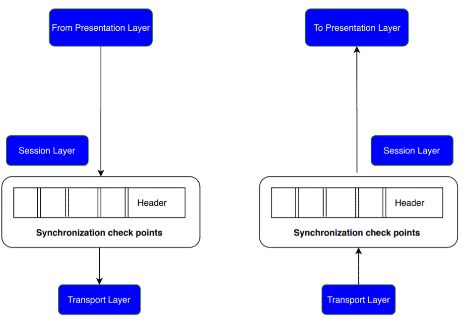
When transmitting data in the form of segments, the session layer adds some synchronization points. If some error occurs, the transmission restarts from the last synchronization point. This process is called synchronization and recovery:
The session layer also plays an important role as a dialog controller. A dialog controller identifies the mode of communication for a session. It allows communication between two systems in half-duplex or full-duplex.
In order to allow applications to communicate with different computers, the session layer uses network protocols like NetBIOS or PPTP.
The presentation layer gives syntax and semantics of the data exchanged between the two networking systems. It provides translations and is also known as a translation layer.
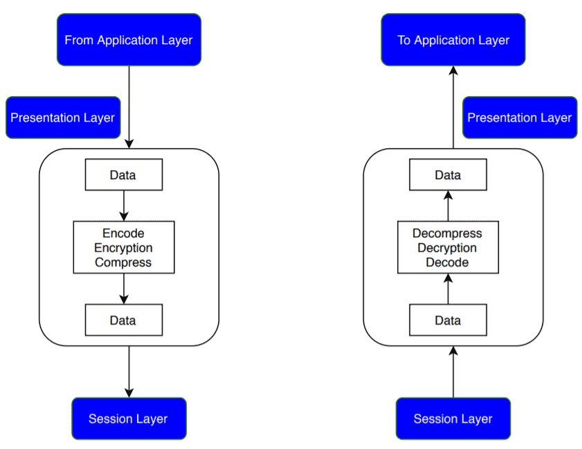
It also ensures data privacy by providing encryption and decryption to the data. It helps in the reduction of the number of bits needed to represent data. This process is formally known as data compression:
In order to ensure the privacy and security of the data being transferred, the presentation layer uses SSL or TSL protocol.
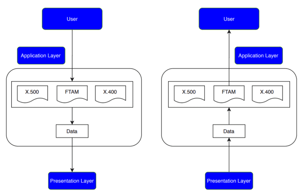
The application layer is the last layer in the OSI model, and it is very close to the software application. It acts as a window between a software application and an end-user. It helps to access the data from the network and display the information to the user.
The application layer performs several functions like it allows a user to access a file remotely, manage the files, retrieve specific data from a computer:
Popular protocols that are used in the application layer are e.g. HTTP, FTP, DNS, SNMP.
In this tutorial, we’ve discussed the OSI model in detail. We presented a concise discussion on each layer of the OSI model with its functionalities.