

Learn through the super-clean Baeldung Pro experience:
>> Membership and Baeldung Pro.
No ads, dark-mode and 6 months free of IntelliJ Idea Ultimate to start with.
Last updated: October 26, 2024
Learn through the super-clean Baeldung Pro experience:
>> Membership and Baeldung Pro.
No ads, dark-mode and 6 months free of IntelliJ Idea Ultimate to start with.
When designing databases, two critical tools we have are Entity Relationship (ER) diagrams and database schemas. Both serve different purposes but are essential for building a functional and efficient database.
In this tutorial, we’ll explore the difference between ER diagrams and database schema. To begin with, we’ll cover ER diagrams in detail. After that, we’ll discuss database schema. Lastly, we’ll look at the difference between the two.
Entity Relationship (ER) diagrams are visual representations of entities and the relationships between them. Moreover, an entity can be anything that needs to be represented in a database. For example, it could be an object, person, or event. Next, the relationships show how these entities interact with one another.
In an ER diagram, we represent entities by rectangles, whereas we represent the relationships between those entities by lines. Primarily, we use these diagrams during the conceptual phase of database design, since they help model how different entities relate to each other.
To illustrate, in a system managing an orchard, we might have two entities: a Tree and an Apple. Let’s look at its representation:
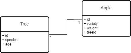
From the above example, we can see that the Tree entity represents the different types of trees in the orchard, while the Apple entity represents the fruits those trees produce. In this scenario, a relationship exists between the Tree and the Apple. Specifically, this relationship could be expressed as a Tree producing multiple Apples, yet an Apple can only come from one Tree.
ER diagrams typically use symbols to describe cardinality, which defines the number of entities involved in a relationship. Common notations are:
For example, a 1:1 relationship might describe a unique partnership between two entities, such as one person being assigned to exactly one car. On the other hand, a 1:n relationship might exist where one Tree grows multiple Apples, but each Apple only belongs to one Tree. Lastly, an n:n relationship might describe a scenario where multiple products can belong to various categories in an e-commerce system.
Many ER diagrams follow specific methodologies, such as the Merise model. In this model, the first symbol, 0 or 1, indicates whether one part of the association is required for the other object to exist.
For instance, if it’s 0, the object can exist without the association. However, if it’s 1, we must associate the object with the other. The second part of the symbol specifies the number of entities allowed in the relationship, either 1 or n.
Using our orchard example again, we can say that a Tree does not need an Apple to exist, but a Tree can produce multiple apples, therefore, it’s 0-n. On the other hand, an Apple must belong to a Tree to exist, but it can only belong to one Tree, hence 1-1.
Let’s consider an ER diagram for a simple blogging platform with the following criteria:
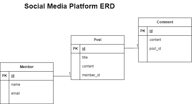
In the above example, the ER diagram helps us visualize how the entities of a blogging platform interact with one another without diving deep into the specific structure of database tables.
In contrast to ER diagrams, a database schema represents the actual construction of a database. It is a detailed blueprint that describes how the database is structured. This includes information about tables, columns, data types, keys (primary and foreign), triggers, and functions.
A database schema is more technical than an ER diagram and is used during the implementation phase of database design. It serves as a guide for database administrators (DBAs) and developers to build and maintain the database.
Where ER diagrams focus on the relationships between entities, the database schema focuses on the tables that store the data. For instance, in a relational database, each entity becomes a table, and the relationships between those entities become foreign key constraints.
Let’s revisit the blogging platform example. The ER diagram outlined the entities and their relationships. Now, the database schema provides the structural details. Let’s look at the requirements first:
The database schema defines the database properties:
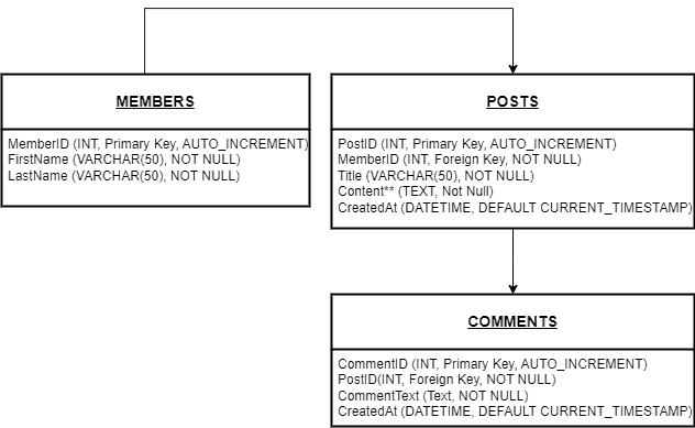
In this schema, we see how each entity from the ER diagram translates into a table in the database. The primary key uniquely identifies each record in the table, while the foreign key ensures that relationships between tables are maintained.
In this section, we discuss several differences between ER diagrams and database schema:
| Aspect | ER Diagrams | Database Schema |
| Purpose | Model relationships between entities at a high level; abstract and conceptual | Represent the technical structure of the database; describe tables, columns, and constraints |
| Focus | Focus on entities and their relationships, emphasizing the business model | Focus on tables and data storage, including relationships through primary and foreign keys |
| Audience | Used by business analysts and system designers to communicate with non-technical stakeholders | Used by DBAs, developers, and technical staff who build and query the database |
| Notation | Uses symbols like rectangles for entities and lines for relationships, with cardinality represented as numbers | Uses SQL tables and enforces relationships through foreign key constraints, in a formalized structure |
| Level of Abstraction | Operates at a higher abstraction level; doesn’t specify data storage details | Detailed and technical, specifying the exact database structure and format |
| Example | Abstract representation of relationships between entities, e.g., Trees and Apples | In the Trees and Apples example, the foreign key TreeID in the APPLES table links Apples to Trees |
In this article, we covered the differences between ER diagrams and database schema. First, we discuss ER diagrams, cardinalities, and relationships in detail. After that, we elaborated on the database schema and its notation. Lastly, we explored the differences between ER diagrams and database schemas.
ER diagrams help us visualize the relationships between entities, making it easier to communicate with stakeholders and model business logic. On the other hand, schemas provide the technical blueprint for implementing the database, defining how we store and manage data.