

Learn through the super-clean Baeldung Pro experience:
>> Membership and Baeldung Pro.
No ads, dark-mode and 6 months free of IntelliJ Idea Ultimate to start with.
Learn through the super-clean Baeldung Pro experience:
>> Membership and Baeldung Pro.
No ads, dark-mode and 6 months free of IntelliJ Idea Ultimate to start with.
UML (Unified Modeling Language) is a modeling language that is used for concisely describing a system. UML diagrams are widely used in the software engineering field.
In this tutorial, we’ll learn how a UML state diagram describes a system and its different states.
A state diagram models the behavior of a system or an object in response to events. A state diagram mainly consists of states, events, guards, transitions, and actions:
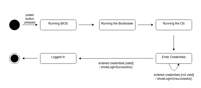
The above diagram shows a state diagram for the booting process of a computer.
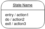
States describe the system’s phase or condition. They are shown by a rectangle with the state’s name written inside it:
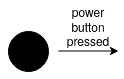
An event can be a signal or a change in the environment of the system. Events may or may not lead to a change in the system’s state:
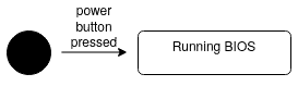
In the above diagram, power button pressed is the event that triggers the transition from the initial state to the Running BIOS state.
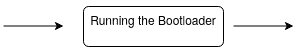
Transitions are shown as arrows from one state to another. They may have three indicators written on them:
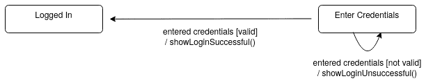
In the above diagram, entered credentials is the event that triggers the transitions, [not valid] and [valid] are guard statements, and showLoginSuccessful() and showLoginUnsuccessful() are actions that are invoked after each transition.
Actions are specific functions that are invoked by the system. There are two types of actions:
They are functions that are invoked after a transition is finished:
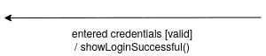
In the above transition, showLoginSuccessful() is a transition action.
State actions are invoked when the system is in a specific state. There are 3 types of state actions:
In addition to the normal states in the state diagram, we may have pseudo-states. Pseudo-states don’t have any specific actions associated with them.
It shows the starting point of the system. It’s represented as a filled circle:
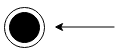
It shows the ending point of the system. It’s represented as a circle with a dot inside:
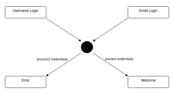
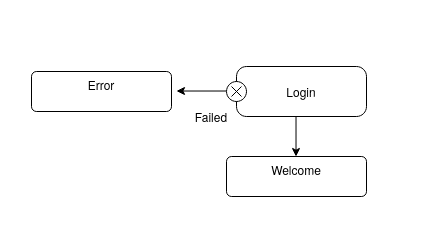
The choice state is represented as a diamond with one arrow arriving and multiple arrows leaving the state. It shows a decision point in the system where the result depends on a condition that is written on every outgoing arrow:

In the above diagram, if the password is correct, the system enters the welcome state, and if the password is incorrect, the system enters the error state.
A junction state combines multiple incoming transitions into one transition. A junction state may have multiple outgoing transitions with different conditions on each one:
In the above diagram, both Email Login and Username Login states enter the same junction state, and if the credentials are correct, the system enters the Welcome state, otherwise it enters the Error state
Fork and join states are used when we have concurrency in the system. Before the concurrent threads are created, a fork state is placed that has one incoming arrow and multiple outgoing arrows that lead to each thread. After the concurrent threads, a join state is placed that links together multiple arrows from each thread into one arrow:
In the above diagram, the first small rectangle is the fork state that leads to the Welcome state. In addition, the second small rectangle is the join state and it’s placed after the concurrent threads of the Welcome state.
Composite states are states that have sub-states. The sub-states form another state diagram inside the composite state:
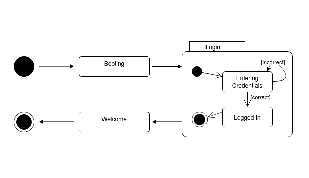
Here, the Login state is a composite state that contains the Entering Credentials and Logged In sub-states.
A composite state may not necessarily start at the initial state and can have a different entry point. Moreover, a composite state may not necessarily end at the final state and can have a different exit point:
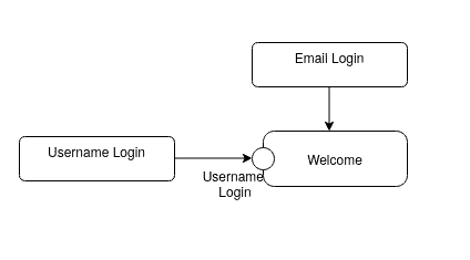
Here, Username Login is an entry point to the Welcome state, and Failed is an exit point from the Login state. The Welcome and Login composite states can look something like this:
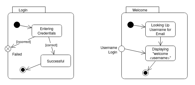
Here, the Login composite state will have a different final point if the entered credentials were incorrect. Moreover, the Welcome composite state may have a different entry point if the user entered their username instead of email.
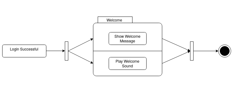
Concurrent states are sub-states of a composite state that are executed concurrently. As we learned, There’s a fork state before the concurrent states and a join state after them:
In the above diagram, the Welcome state has two sub-states that run concurrently: Show Welcome Message and Play Welcome Sound.
Sometimes the object must remember where it left off. In these situations, a history state is used to show the memory of the object. If, for any reason, the system is interrupted, it can remember where it left off the next time it starts running.
A history state is shown by a capital H inside a circle:
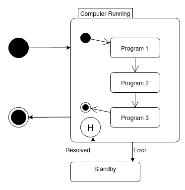
Here, the computer starts running the programs and if an error occurs, it enters the standby state. After the error is resolved, the computer starts where it left off until all the programs are successfully executed.
In this tutorial, we learned about the components and syntax of a UML state diagram.