Learn through the super-clean Baeldung Pro experience:
>> Membership and Baeldung Pro.
No ads, dark-mode and 6 months free of IntelliJ Idea Ultimate to start with.
Last updated: March 26, 2025

Learn through the super-clean Baeldung Pro experience:
>> Membership and Baeldung Pro.
No ads, dark-mode and 6 months free of IntelliJ Idea Ultimate to start with.
In this tutorial, we’ll discuss the mechanism of IP fragmentation and reassembly of IP version 4 packets, two important data transmission concepts in IP networks.
Data transmission in IP networks has as its basic unit IP datagrams. To date, we’ve known two versions of IP networks: IPv4 and IPv6. We’re interested in IPv4 datagram since IP fragmentation and Reassembly only occur in the 4th IP version. An IPv4 datagram consists of an IP header and a payload and is used to transmit data between devices over a network.
The header can be divided into seven major parts, and each part can be further divided into sub-parts if the information it carries needs further specification. Each part provides information concerning the packets that are transmitted.
In every physical network, a Maximum Transmission Unit (MTU) size is specified, i.e. the maximum size of a data packet or frame that can pass through a specific Network Interface Card (NIC). So, different networks a data packet can traverse may have heterogeneous MTU sizes
If, for example, a packet comes from a network, say A, with a bigger MTU size than the one the packet is transiting to, then the packet must be fragmented. The fragmentation process here consists of breaking down a larger IP packet into smaller packets that can be transmitted over the new network with a smaller MTU size.
IP fragmentation is, therefore, the process of breaking down a larger IP datagram into smaller packets (fragments) that can be transmitted over networks with smaller maximum packet sizes. It is performed either by the computer that initiates the transmission (the sender) or by intermediate routers.
Talking about data transmission, if we have a packet greater than the size of the MTU, it needs to be fragmented into smaller pieces called fragments. The fragments will transit over the network to reach their destination. A mechanism put in place within the datagram helps to number the fragments from 1 to the total number of fragments. While transiting over networks, some fragments go over the same path during the routing process.
Actually, depending on the state of the routers, checked into their various routing tables, packets arriving at a router do not always follow the path even if they have the same destination. Thus, it can happen that fragment number 6 reaches the destination before fragment number 2. The fields identification, flags, and fragment offset are in charge of ordering them so that the destination can recover the packet easily:
It is a 16 bits field that indicates a value that aids in identifying the fragments of a fragmented IPv4 data packet. It means that all the fragments of a fragmented datagram have the same identification number, which will be used to identify IPv4 fragments on the receiving side. The identification is a unique number unique for the combination of source and destination address values, allowing the destination to distinguish between the fragments of different packets from the same source. For example, if let’s say two packets are sent from one computer to another over the network, and each of these packets must be fragmented into three fragments,
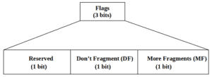
This three-bits field controls fragments and indicates fragmentation possibilities. The first bit has been reserved for future use and always has a value of zero. The next bit DF when set to the value “0” indicates that the datagram can be fragmented if necessary.; and when set to “1”, the datagram can not be fragmented even if required. In this case, the packet is destroyed, and an ICMP message is returned to the sender. In the last bit, MF indicates if the packet has more fragments to come. When set to “1”, more fragments will follow the packet, and when set to “0”, it means that either no more fragments will follow or the packet was not fragmented.
It is a 13-bit field that is used to identify the starting position of data in a fragment concerning the start of the data in the whole datagram. It indicates the position of a fragmented datagram in the original unfragmented IP datagram. The first fragment datagram has a fragment offset of zero. The fragment offset, like the identification and Flags fields, is used to reassemble the datagram from all the fragments.
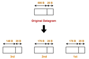
Practically, in the first fragment, the offset is 0, as the data in this packet starts in the same place as the data in the original packet (at the beginning). The fragment offset is measured in units of 8 octets (64 bits). So, in subsequent fragments, the value is the offset of the data that the fragment contains from the beginning of the data in the first fragment in 8 bytes blocks step. For example, if a packet contains 500 bytes of payload data and a MTU of 176 bytes, it will be fragmented into 3 fragments. The two first have 176 bytes and the last one has 148 bytes.
With the identification, flags and Fragment offset fields, we can reassemble the full datagram packet at the destination host.
IP fragmentation can be performed by the sender or intermediate routers, and the fragments are reassembled at the destination device. This reassembly involves combining the fragments in the correct order based on information in the IP headers, such as the fragment offset and the identification number we saw in the previous section.
A fragmented datagram has multiple fragments that are transiting over the network. At the destination, the overall message must collect and reassemble all the fragments to recover the original message. Reassembly is performed by using the three fields used during the fragmentation process.
We’re putting emphasis here on the fact that even if intermediate routers can fragment or further fragment an already fragmented frame, they’re not able to perform reassembly. to reassemble the original packet, the destination host will use the identification number of fragments to identify those belonging to the same datagram, then the fragment offset field to order the data from the beginning til the end.
Several implementation issues are associated with IP fragmentation and reassembly. The main implementation issues include:
| N° | Implementation issue |
|---|---|
| 1 | Fragmentation is time-consuming and thus, performing it may result in significant delays while delivering packets and even loss of packages |
| 2 | Fragmentation involved in communication can increase bandwidth usage and therefore lead to congestion which can paralyze a network |
| 3 | Incorrect or inconsistent implementation of the fragmentation and reassembly process can result in lost or corrupted data, which can affect the accuracy and reliability of communications |
| 4 | Security considerations: fragmented packets can be used in denial-of-service (DoS) attacks, where an attacker intentionally sends fragmented packets to overwhelm a target network or system. This can potentially disrupt network operations and lead to outages |
These are some of the main implementation issues related to IP fragmentation and reassembly; however, there may be additional issues depending on the specific implementation and network configuration.
In this article, we’ve presented the concept of IP fragmentation and reassembly by describing various fields of an IPv4 datagram packet. We have further discussed the fields involved in fragmentation and reassembly. We have ended by listing some of the main implementation issues encountered by fragmentation and reassembly in IP networks.