Learn through the super-clean Baeldung Pro experience:
>> Membership and Baeldung Pro.
No ads, dark-mode and 6 months free of IntelliJ Idea Ultimate to start with.
Last updated: July 25, 2024

Learn through the super-clean Baeldung Pro experience:
>> Membership and Baeldung Pro.
No ads, dark-mode and 6 months free of IntelliJ Idea Ultimate to start with.
In this tutorial, we’re going to look at how the arithmetic logic unit (ALU) works and how computers calculate through the ALU. We’ll also use logic gates to build a simple ALU.
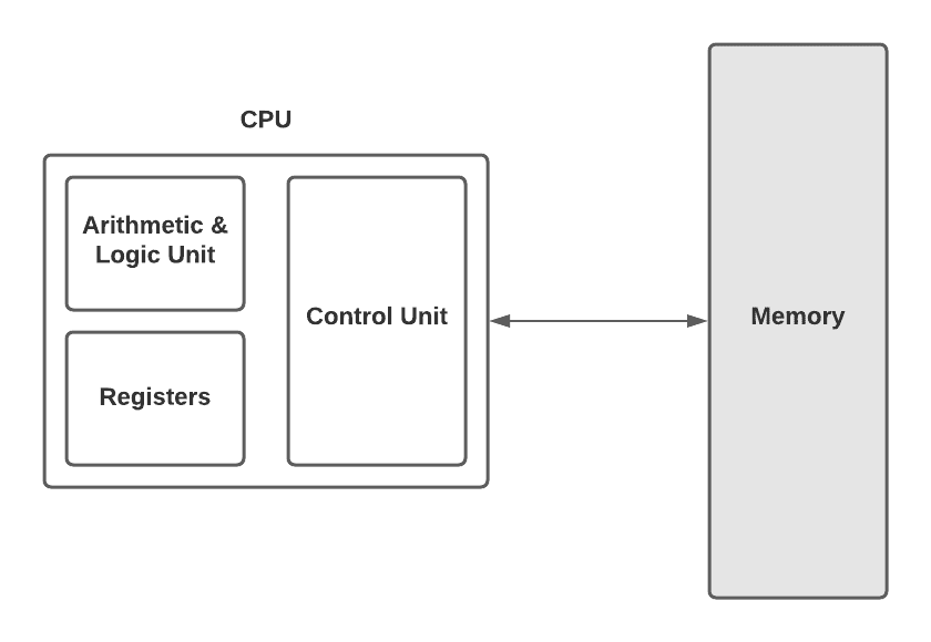
If we look at the figure below, we can see the abstraction between the central processing unit (CPU) and the memory. Registers and RAM have a crucial role in storing data. However, computation and manipulating numbers are other paramount principles in low-level circuits. The ALU performs these kinds of operations. It’s the mathematical brain of a computer:
Once we realize how the ALU works, we’ll understand a fundamental part of modern computers. Since the ALU does all the computation in a computer, all modern computers use it. Before using logic gates to build our basic ALU, let’s take a look at a famous ALU, the Intel 74181, in the figure below:
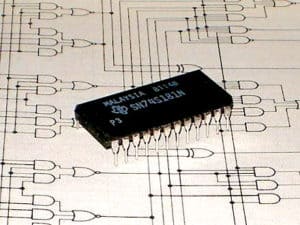
The 74181 is the first complete ALU on a single chip. Many historically significant computers and other devices have used it as the ALU core in their CPUs. Computer organization textbooks and some technical papers still refer to it. It’s also used in hands-on courses, such as logic design, to train future computer architects.
As we mentioned earlier, an ALU has two units, the arithmetic unit, and the logic unit. The arithmetic unit is responsible for all numerical operations in a computer, such as addition and subtraction. It also operates other simple things like increment operation.
Let’s build an adding circuit that takes two binary digits and adds them together. We’re going to use AND, OR, XOR, and NOT logic gates. We have two inputs,  and
and  , and one output, which is the sum of two digits. As we said,
  ,
,  , and the output are all single bits. In this case, there are only four possible input combinations. The first three are:


As we know, in binary, 1 is the same as true and 0 is the same as false. So it’s obvious that these inputs and outputs are exactly the same as the logic of an XOR gate. We can use it as a 1-bit adder. However, the fourth input combination,  , is a special case. It’s obviously 2, but there are no 2 digits in binary. So the result is 0, and the 1 is carried to the next column; the sum is really 10 in binary.

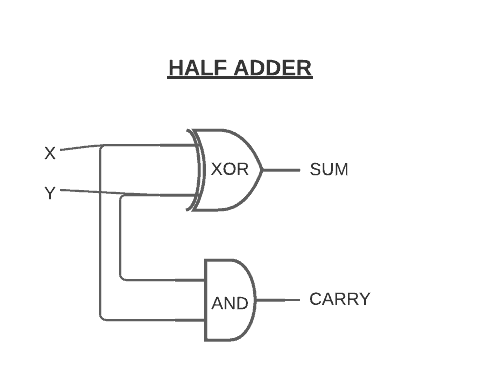
To have this “carried” 1 in the circuit, we’ll need an AND gate and an extra output wire for that carry bit. This is because the carry bit is only equal to 1 when both of the inputs are equal to 1. We call this whole circuit a half adder, as the figure depicts below:
If we want to add more than 1 + 1, we’ll need a full adder. To understand how we use half adders to build up a full adder, let’s take a look at the table below:
| X | Y | Z | CARRY | SUM |
|---|---|---|---|---|
| 0 | 0 | 0 | 0 | 0 |
| 0 | 0 | 1 | 0 | 1 |
| 0 | 1 | 0 | 0 | 1 |
| 1 | 0 | 0 | 0 | 1 |
| 0 | 1 | 1 | 1 | 0 |
| 1 | 0 | 1 | 1 | 0 |
| 1 | 1 | 0 | 1 | 0 |
| 1 | 1 | 1 | 1 | 1 |
As we can see in the table above, the full adder takes three bits as inputs: , , and  . Therefore, the maximum possible input is 1 + 1 + 1. It equals 1 carry out 1. We still need two output wires for sum and carry.
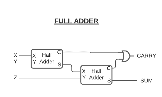
To simplify the complexity of circuits, we’re going to represent a half adder, like in the figure below. It represents how we can build a full adder to add more than 1 + 1 using a half adder:
Now that we have a full adder and a half adder, we can build a circuit that takes two 8-bit numbers. Let’s call them and . We can use a half adder for the first two bits, and then full adders for the rest of the bits, like in the figure below:
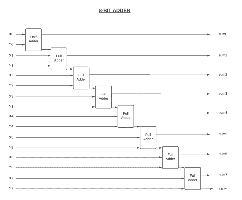
If we take a look at the figure above, we can see that there’s a carry bit into the ninth bit. This is called overflow. It occurs when the result of an addition is too large to be represented by the number of bits we’re using. This can lead to errors and unexpected results.
If we want to get rid of overflows, we can extend our circuit with more full adders. Doing so allows us to add 16 or 32-bit numbers. This decreases the chance of overflow on the operations while increasing the complexity of the circuit. That’s why today’s computers use little different adding circuits. We call it a carry-look-ahead adder. Even though it’s faster, it does exactly the same thing.
The arithmetic unit has circuits for other math operations like subtracting, negating, incrementing, and decrementing. However, it doesn’t have any circuits to perform multiply and divide operations. This is because it performs a series of addition instead of multiplication. Although simple processors, like those in our TV remote and air conditioner, do multiplication using addition, more complicated processors, like those in our laptops and smartphones, have more dedicated multiplication circuits.
Now we can continue with the other half of the ALU, the logic unit. The logic unit handles logical operations like AND, OR, and XOR, instead of arithmetic operations. It also performs numerical tests. For example, it checks whether the number is negative or not. It also controls if the output of the ALU is zero.
As we’ve seen, even our 8-bit adder requires tens of logic gates. Therefore, an 8-bit ALU would require hundreds of logic gates to fully build. To get rid of all that complexity when using the ALU, we use the symbol that represents the ALU. We can see the ALU symbol in the figure below:
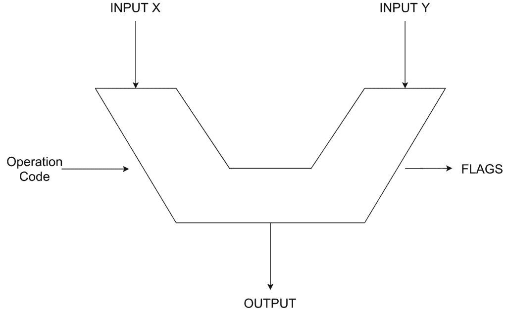
It has two inputs, , and , and the operation code specifies what operation the ALU will perform, such as subtraction or addition. The result of that operation on inputs and is an 8-bit output. It also has a series of flags, such as overflow, zero, or negative. These flags help us out by checking whether the output is zero or not, and determining which input is bigger than another one. As we learned, overflow is connected to carry out on the adder that we built.
In this article, we discussed how the computer does all of its basic mathematical operations. We touched briefly on the history of the ALU and then shared how to build an 8-bit adder step by step. We also explored how the ALU works under the hood, and we learned how to build a half adder and a full adder using logical gates.